I don’t have a blog post about ‘what is VMware NSX-T‘ yet -I’ll create a more extensive one in the future- but I just needed to share this with the world. I wanted to deploy a so-called ‘One-Arm Load Balancer attached to segment VLAN ‘ but I just couldn’t get it to work. In this blog, I’ll explain the theory about why it didn’t work, how the configuration should be to work and how I managed to actually deploy the load balancer so it did work.
Table of Contents
In short- what is VMware NSX?
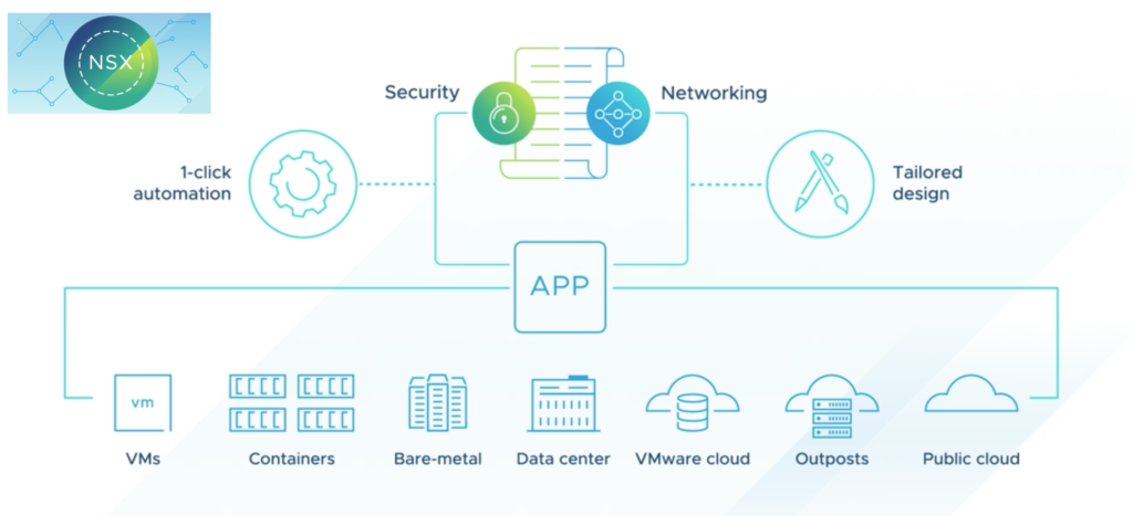
I’ve written a previous blog about what VMware ESXi does but I don’t have a blog explaining VMware NSX. In short, where VMware ESXi does computer virtualization, VMware NSX does something similar but then for the network. VMware NSX provides two main functions, the first function is Network Function Virtualization (NFV) which means that devices that are normally physical, for example, a router or load balancer, are now virtualized and made available as a service to the virtual environment. The second function is that NSX helps with securing the environment with the means of the Distributed FireWall (DFW). I understand that this all may sound very abstract and I can assure you, it is. In the future, I’ll write some more extensive blogs about VMware NSX functions, adding some more much-needed details. For now, we’ll focus on the first main feature: NFV.
The VMware NSX-T load balancer
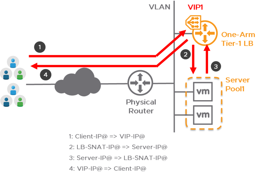
The goal of this exercise is simple- use the NSX-T load balancer to divide visitors over multiple web servers. Now, there are multiple topologies available for deploying a -VMware NSX- load balancer- however- most topologies depend on the use of a technology called ‘Overlay‘ networking. Since I neither want to use any overlay networking nor any distributed firewall functions, there is only one possible topology left: the so-called ‘One-Arm Load Balancer attached to VLAN segment‘ and that is what this blog is about.
After seeing this topology I’ve deployed two Edge nodes, created the needed Tier-1 Gateways and linked them to the Edge node cluster, and then added the load balancer. After some time the deployment of the load balancing service displayed the status ‘Error‘ with the remark ‘lbServiceStatus is ERROR‘. I started to look if the deployment of the Tier-1 Gateway is still good but that is showing the status ‘down‘. Now, this isn’t supposed to happen -so somewhere it all went horribly wrong.
To troubleshoot, I started digging through the syslog logging of the Edge that should be hosting the load balancer- but I couldn’t find any real error. There are many, many, many log lines in the syslog so I can imagine that my search query is too narrow, filtering out the actual fault. The command shown below will only show logging of the NSX subcomponent load balancer but I couldn’t find an error with this.
» Click here to show the syslog output
root@nsxedgelb01:~#  cat /var/log/syslog | grep "subcomp=\"lb\""
2021-11-15T16:15:58.323363+00:00 nsxedgelb01.lab02.wheatley.local NSX 10097 LOAD-BALANCER [nsx@6876 comp="nsx-edge" subcomp="lb" s2comp="lb" level="INFO"] [ed1954a5-d515-4850-848d-9b509e933e3f] cfg: engine config [version: 1] processing - stage 1/6 successful
2021-11-15T16:15:58.332662+00:00 nsxedgelb01.lab02.wheatley.local NSX 10097 LOAD-BALANCER [nsx@6876 comp="nsx-edge" subcomp="lb" s2comp="lb" level="INFO"] [ed1954a5-d515-4850-848d-9b509e933e3f] cfg: engine config [version: 1] processing - stage 2/6 successful
2021-11-15T16:15:58.343753+00:00 nsxedgelb01.lab02.wheatley.local NSX 10097 LOAD-BALANCER [nsx@6876 comp="nsx-edge" subcomp="lb" s2comp="lb" level="INFO"] [ed1954a5-d515-4850-848d-9b509e933e3f] cfg: engine config [version: 1] processing - stage 3/6 successful
2021-11-15T16:15:58.424428+00:00 nsxedgelb01.lab02.wheatley.local NSX 10097 LOAD-BALANCER [nsx@6876 comp="nsx-edge" subcomp="lb" s2comp="lb" level="INFO"] [ed1954a5-d515-4850-848d-9b509e933e3f] cfg: engine config [version: 1] processing - stage 4/6 successful
2021-11-15T16:15:58.439171+00:00 nsxedgelb01.lab02.wheatley.local NSX 10097 LOAD-BALANCER [nsx@6876 comp="nsx-edge" subcomp="lb" s2comp="lb" level="INFO"] [ed1954a5-d515-4850-848d-9b509e933e3f] cfg: engine config [version: 1] processing - stage 5/6 successful
2021-11-15T16:15:58.465289+00:00 nsxedgelb01.lab02.wheatley.local NSX 10097 LOAD-BALANCER [nsx@6876 comp="nsx-edge" subcomp="lb" s2comp="lb" level="INFO"] [ed1954a5-d515-4850-848d-9b509e933e3f] cfg: engine config [version: 1] processing - stage 6/6 successful
Why is the overlay needed?
After trying different configurations and searching online together with a college we came across an ‘NSX-T LB Encyclopedia‘ by Dimitri Desmidt. In this Encyclopedia, there is a single remark on slide 7 that reads “[…] Edge Nodes must have at least 1 tunnel up to get its LB hosted Standalone T1 Active.“. This remark triggered me and I started thinking about why an overlay network would be needed. The load balancer is deployed on a Tier-1 gateway which is partly a service provided by the ‘Edge nodes’ that are deployed by NSX. Yes- multiple nodes– they are, for high availability reasons, usually deployed as at least a pair in an edge node cluster.
Could it be that the Edge nodes need a special link to communicate? This would explain the deployment failure of the T1 gateway and the load balancers. I found in the logging that this is indeed the way it works- the link is used for communication about their status (HA). While investigating, I even got a greater surprise. It seems to me that NSX creates not just one, but two tunnels between the Edge nodes. One tunnel is created via the underlay network (10.10.80.xxx) and the second HA tunnel is created via the Overlay network (172.16.21.x). It’s not really a gamechanger but it is definitely nice to get an even better understanding of how VMware NSX works.
nsxedgelb01> get log-file syslog | find "ha-cluster"
2021-11-19T09:27:42.932Z nsxedgelb01.lab02.wheatley.local NSX 17 FABRIC [nsx@6876 comp="nsx-edge" subcomp="nsxa" s2comp="ha-cluster" level="INFO"] HA tunnel 172.16.21.1:172.16.21.2 state changed from Concat Path Down to Unreachable
2021-11-19T09:28:10.011Z nsxedgelb01.lab02.wheatley.local NSX 17 FABRIC [nsx@6876 comp="nsx-edge" subcomp="nsxa" s2comp="ha-cluster" level="INFO"] HA tunnel 10.10.80.101:10.10.80.102 state changed from Admin Down to Unreachable
I’ve recorded the console output of my session with NSX edge- nsxedgelb01. Here I show the High Availability status, show the present Virtual Routing and Forwarding (VRF’s), and all interface information.
How to configure the load balancer so it will work?
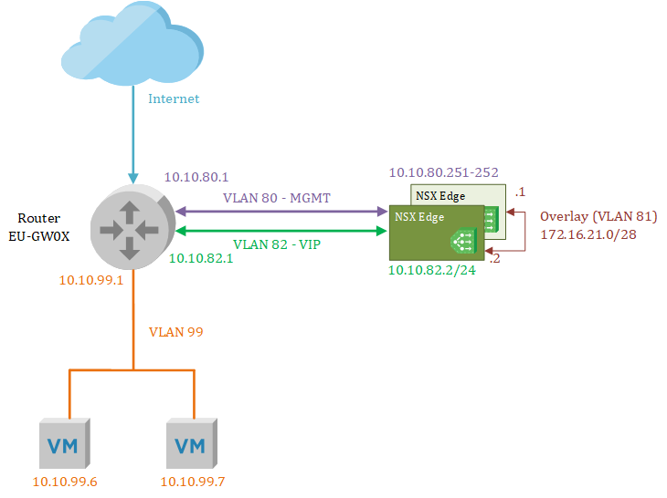
To show you what I did to get the topology to work- I’ve created the overview below. In this overview, there are two load balancers -deployed in two NSX Edges- in an active/standby configuration with an overlay tunnel between them to exchange status information. The actual web servers are located in VLAN 99 and to reach them the load balancer will send that traffic to the router. Next to the Overlay and VIP address interfaces, there’s a separate interface that will be used for management tasks.
Creating the prerequisites in the NSX-T manager
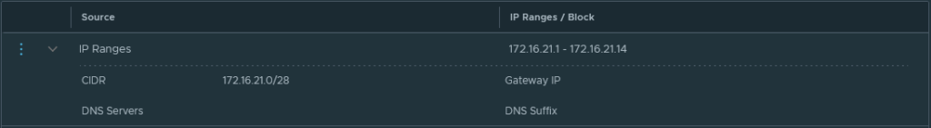
Let’s start building the configuration, these prerequisites will be needed at a later stage to deploy the NSX Edge nodes. First I created an IP pool that is needed for the overlay Tunnel End Point (TEP) interfaces. In my case, I decided to use VLAN 81 for any overlay communication and I dedicated the 172.16.21.0/28 IP space for the TEPs.
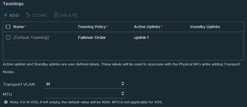
Next, an ‘uplink’ profile is needed to give additional information about the overlay network. Here I fill in that that VLAN 81 will be the transport VLAN and because this is a ‘One-Arm‘ load balancer, one uplink interface will suffice. The MTU field will be left empty which means it will be set at the default 1600 which is needed for the GENEVE network encapsulation protocol.
Then there are two ‘Transport Zones’ needed. It’s also possible to use the default transport zones that come with VMware NSX but I’ve decided to not always use the default profiles but to add my own. Therefore I’ve added two transport zones, one for VLAN and one for Overlay.

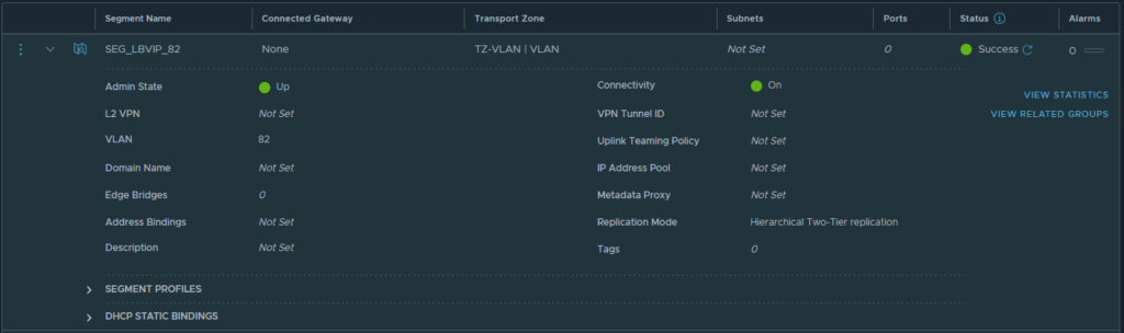
With the transport zones created, I added a ‘segment’ that will host the Virtual IP (VIP) addresses for the load balancer. The VIP address is the address that is used by the clients to reach, in this example, a website that is load balanced. I’ve decided to use VLAN 82 for these addresses and I created an NSX segment on the VLAN transport zone accordingly.
Deploying the NSX-T Edge Nodes
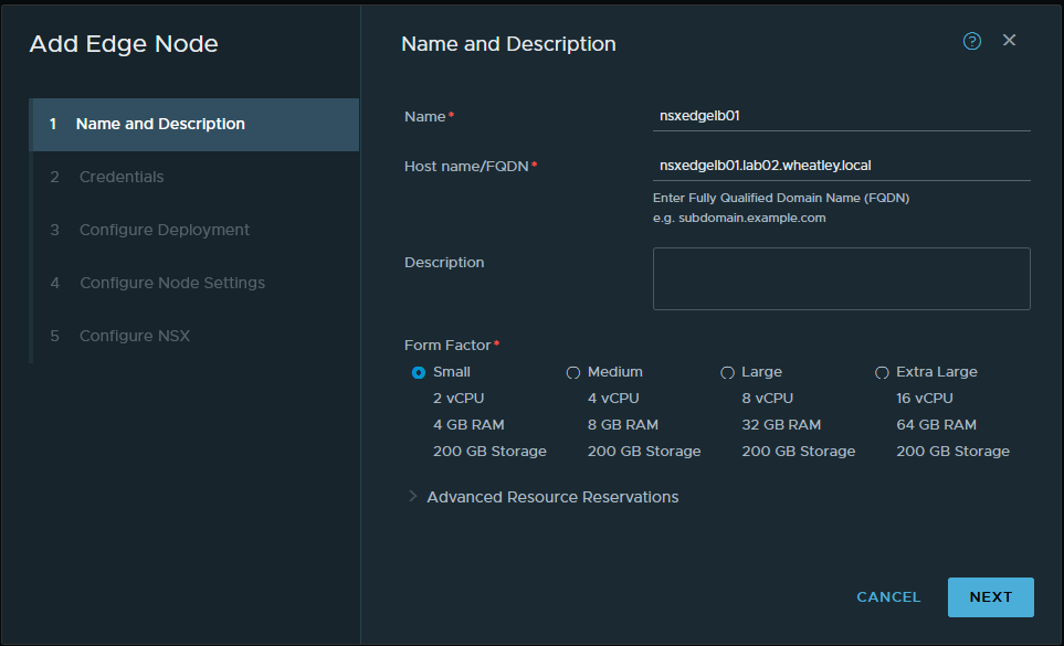
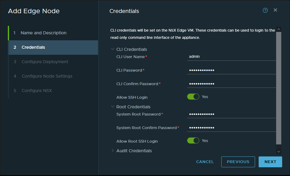
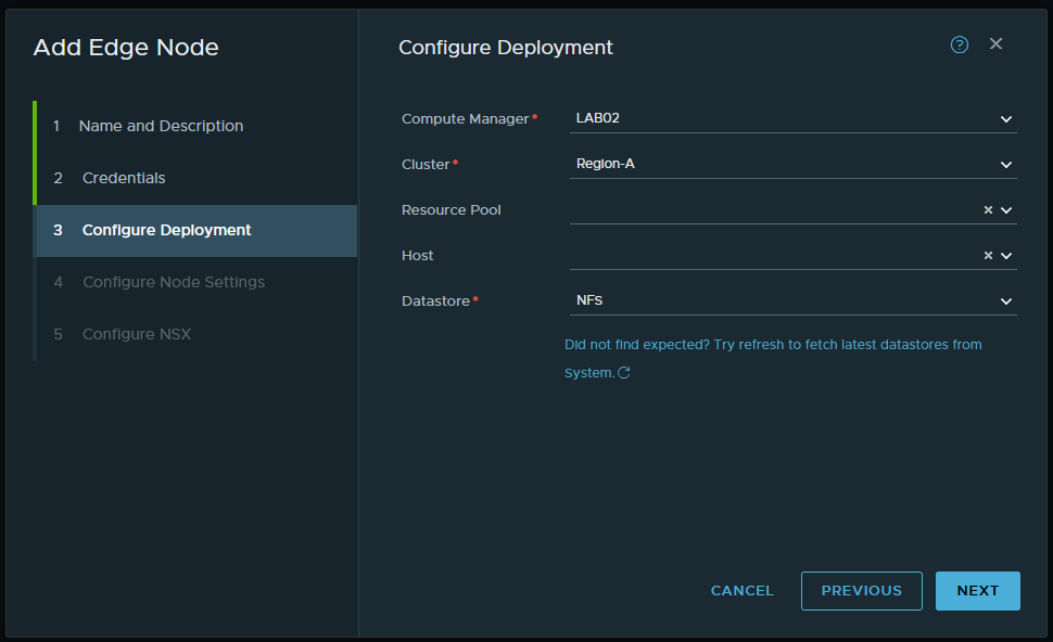
Okay, the prerequisites are now in place, time to get started with deploying the NSX-T Edge nodes that will host the load balancer. The configuration is quite basic at first, give the VM a name -nsxedgelb01-, fill in the full FQDN, and select a form factor -this being my lab- I’ll deploy two ‘small‘ sized edge nodes. On the next page, I filled in a strong password and I’d like to be able to SSH into the node so I’ll turn on that option as well.
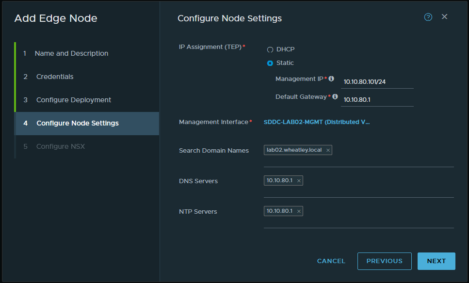
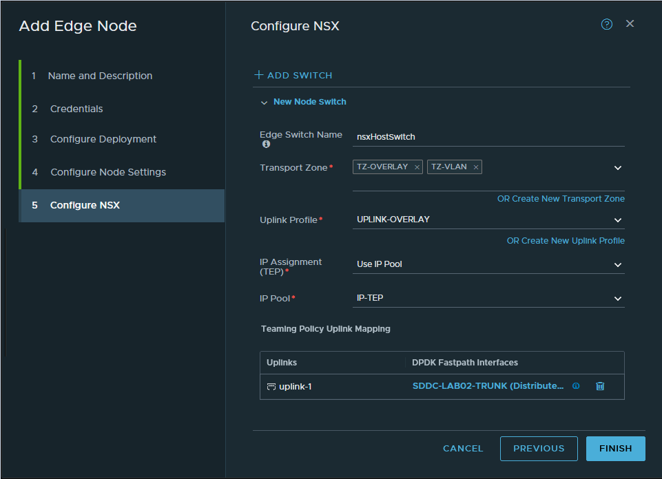
In the next tab ‘Configure Node Settings‘ I configure the management settings for this specific node and continue on to ‘Configure NSX’. This is the most important page during the deployment! I configure which transports zones should be attached to the Edge, these are the VLAN and the Overlay transport zones. Because of the Overlay, we need to configure the IP assignment where I can use the earlier created IP-TEP pool. After selecting the right Uplink profile I can map the Edge node to the TRUNK interface that allows all VLANs. While the deployment of nsxedgelb01 is in progress, I repeat the process for nsxedgelb02.
In the vCenter of LAB02, I can see that the OVF templates of nsxedgelb01 and nsxedgelb02 are deployed and powered on which is exactly what is needed. At this time I took a short break because this process will take some time to complete, roughly 10 ~ 20 minutes, depending on your hardware.

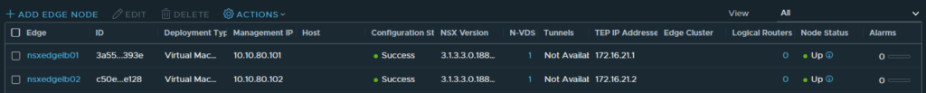
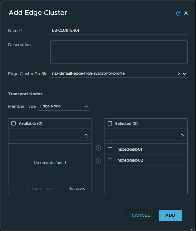
After the deployment finishes, the overview in NSX refreshes to reflect the status of the Edge nodes. Please, be aware that since the nodes are not yet in a cluster, the tunnel status will show ‘Not Available‘. This status is to be expected and the next thing to do is to configure an Edge cluster with the name ‘LB-CLUSTER01’. After a short while, the Edges now show that they both have one tunnel up. So far so good!

Deploying the Edge services
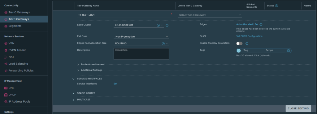
The edges are still empty shells that need more configuration- how it exactly works I’ll cover in an next blog. For now, it’s good enough to know that the NSX load balancer is actually running from a ‘Tier-1 Gateway‘ which I will name ‘T1-TEST-LB01’. I’ll link that T1 Gateway to the earlier created Edge cluster ‘LB-CLUSTER01’. With the T1 Gateway deployed some more configuration will needed.
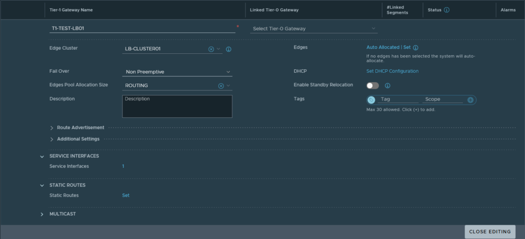
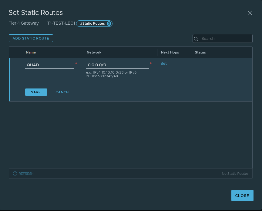
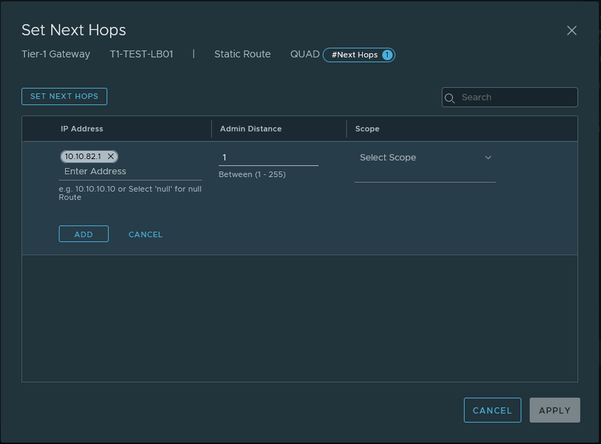
The network traffic to and from the VIPs will use the ‘Service Interface‘ and that will be linked to the earlier created segment ‘SEG_LBVIP_82‘. The service interface will use ‘10.10.82.2/24’ as an IP address and to make sure that network traffic on that interface gets to find the way out of the network again a ‘Static Route’ is configured to point to the router.
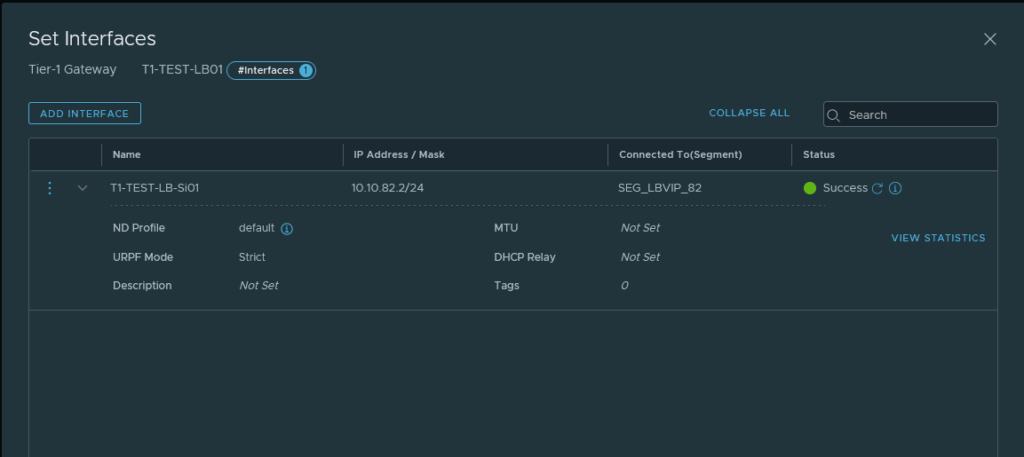
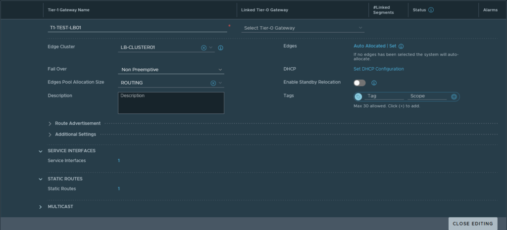
If all goes well the status should reflect ‘Success’, this could take up to a minute for the UI to show though. After refreshing multiple times and waiting for a while the status is still ‘Success’, meaning progress!

Deploying the Load Balancer
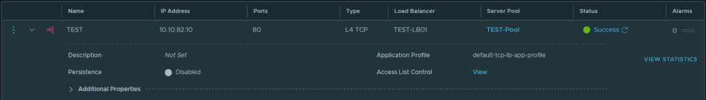
There is already a lot of configuration present in the NSX manager and we’re almost there. Just a few more steps are needed to configure the load balancer. To deploy the load balancer the configuration is quite simple. I filled in the following; the name -TEST-LB01-, the size -small- and attach it to the earlier created T1 -T1-TEST-LB01. The deployment can take a couple of minutes so give it some time but it should now come back with the status ‘Success’ and again it stayed that way.

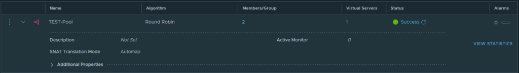
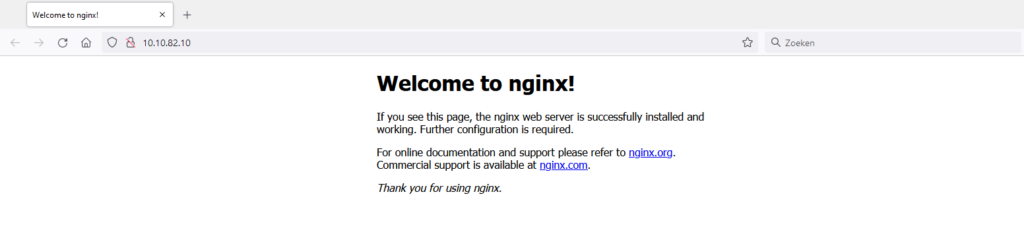
At this point, I was already extremely happy -progress at last. I just wanted to have proof that the load balancer is working indeed. I quickly created a ‘TEST-pool’ that holds both NGINX webservers and I’ve added the Virtual Server with the name ‘test’ that is running on the IP address 10.10.82.10 on port 80 (HTTP) got into the browser and voilá it all works!
Closing thought
In the end, it took a while to find the reason why the load balancer wasn’t deploying as I expected. After an extensive search, I found the clue to make sure the Edge has a tunnel that has the status ‘up’. The tunnel is not easily visible in the syslog if it’s even mentioned at all. This exercise gave me a better understanding of the NSX load balancer works and how to deploy the load balancer where no overlay networking is used for connectivity but a VLAN.
Thanks for reading! Hopefully, you found it interesting and maybe you’ve even learned something new! Want to be informed about a new post? Subscribe! Any questions or just want to leave a remark? Please do so- I’m always very curious to hear what you think of my content. Enjoy your day!